Since 1953, CROM has designed and built 4,800 prestressed concrete tanks (PCTs) with capacities ranging from 35,000 to over 30,000,000 gallons. CROM adheres to the highest standards of professional engineering and construction including AWWA Standard D110, ACI Report 372, and ACI Code 350. As long-term active and contributing members of both design committees, CROM remains a leader in the water and wastewater industry. All CROM design drawings and calculations are signed and sealed by one of our company’s full-time registered professional engineers.
Please Note: All engineering services are performed by CROM, LLC.
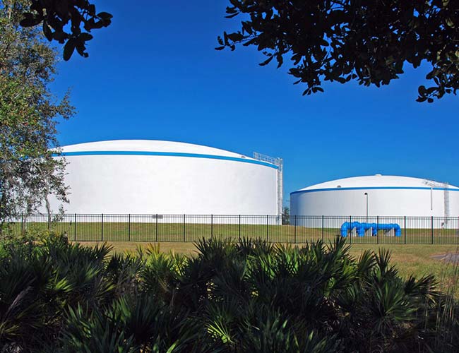
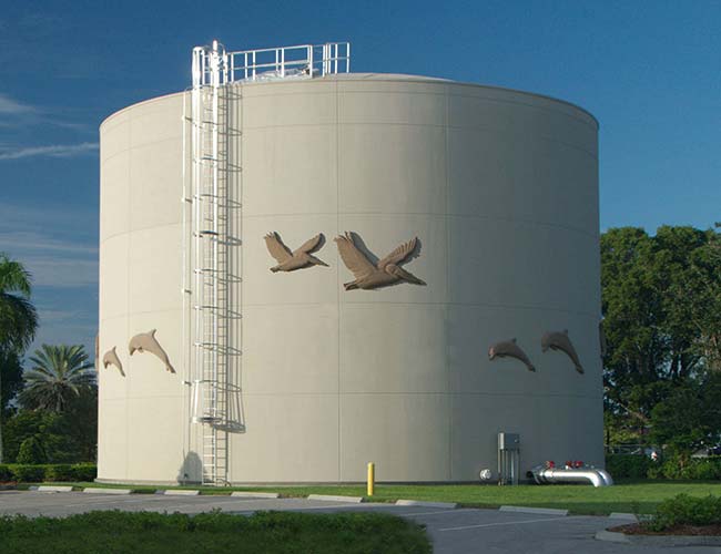
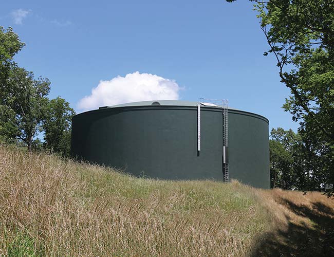
PCT Applications
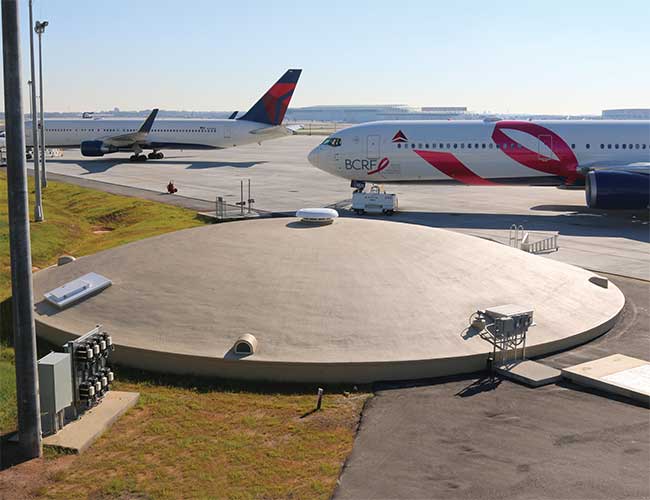
WATER STORAGE
TANKS
THERMAL ENERGY
STORAGE
Fire protection
TANKS
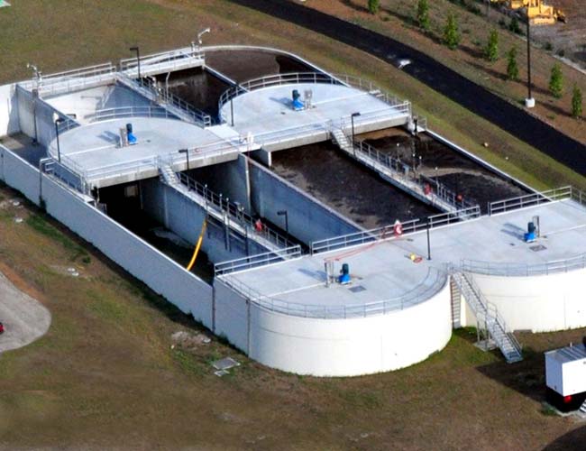
CIRCULAR WASTEWATER
PROCESS TANKS
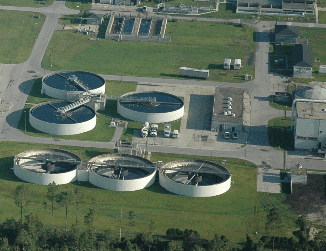
OVAL WASTEWATER
PROCESS TANKS
UNIQUE
TANKS
PHASES OF prestressed concrete tank CONSTRUCTION
1
CASTING THE FLOOR
casting the floor
The foundation of the prestressed tank is typically a heavily reinforced thin membrane concrete slab. Structural and ballast floor designs are also common, depending on site condition requirements.
2
DIAPHRAGM
Diaphragm
Galvanized steel shell diaphragm is erected on a system of formwork specially designed for this purpose. The steel shell extends the full height of the tank to ensure watertightness. Vertical joints in the steel shell are sealed watertight by epoxy injection.* U.S. Patent No. 5,150,551
3
OUTSIDE CORE WALL
outside core wall
Exterior encasement of the steel shell is accomplished with shotcrete, which is pneumatically placed concrete. The core wall of the tank is constructed using successive layers of shotcrete until the required wall thickness is achieved.
4
INSIDE CORE WALL
inside core wall
After the formwork system is removed from the tank interior, shotcrete is applied to encase the diaphragm and complete the interior core wall.
5
DOME SHELL FORMING & CASTING
dome shell forming & casting
The free-span concrete dome roof is made possible with the aid of a forming system that ensures accurate dome curvature. The free-span dome roof is then constructed of cast-in-place concrete.
6
PRESTRESSING
prestressing
Both the core wall and dome ring band are circumferentially prestressed using high-strength steel wire wrapped around the tank in a continuous helix. To avoid over-stressing or under-stressing of the tank, wire tension is measured via an electronic digital stressometer applied to the tank wall.
7
SHOTCRETE OVERCOAT
shotcrete overcoat
To protect the prestressing elements, a shotcrete covercoat is applied to the exterior, which permanently bonds the wire to the tank wall. The covercoat completes the concrete portion of the tank construction.
8
TANK ACCESSORIES
tank accessories
The final stage of construction involves installation of accessories and if desired, application of exterior coatings for decorative purposes.